Table of Contents
Smart City Batteryless, Wireless and Serviceless Sensor Node
Design assumptions
The aim of this project is to build batteryless and serviceless device for measuring passing cars count and speed.
The project is not finished due to lack of essential parts (radio quartz and inductor for boost converter).
Still I think it is cool therefore I am posting it.
Applications
- Intelligent traffic control
- Industrial sensor networks
- Security systems
- Intelligent lighting
- Crowd management
System does not have to be limited to the cars. Piezo sensors can detect any moving mass including both vehicles and humans.
Location
<html> <?xml version=“1.0” encoding=“UTF-8” standalone=“no”?> <!– Created with Inkscape (http://www.inkscape.org/) –>
</html>
Device can be located under asphalt. The piezo generators will be located under track of car wheels. The wireless link with local wired node allows for minimum invasion into road structure.
Block diagram
<html> <?xml version=“1.0” encoding=“UTF-8” standalone=“no”?> <!– Created with Inkscape (http://www.inkscape.org/) –>
</html>
The mechanical energy from the passing cars is transformed using piezoelectric transducers into electric power. The current is rectified and boosted in high-efficiency, low input voltage boost converter. The energy is stored in capacitor. Other sources of energy can be connected as well.
MSP430 is in deep sleep until external interrupt wakes it up. Radio is completely cut off from the power unless MCU opens MOSFET.
Experiments
Alongside hardware development I am experimenting with the piezoelectric power generation.
I am using 35 [mm] Piezo plates:
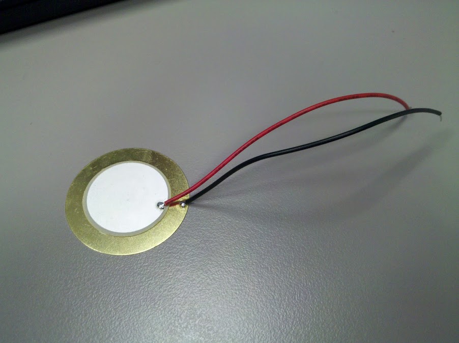
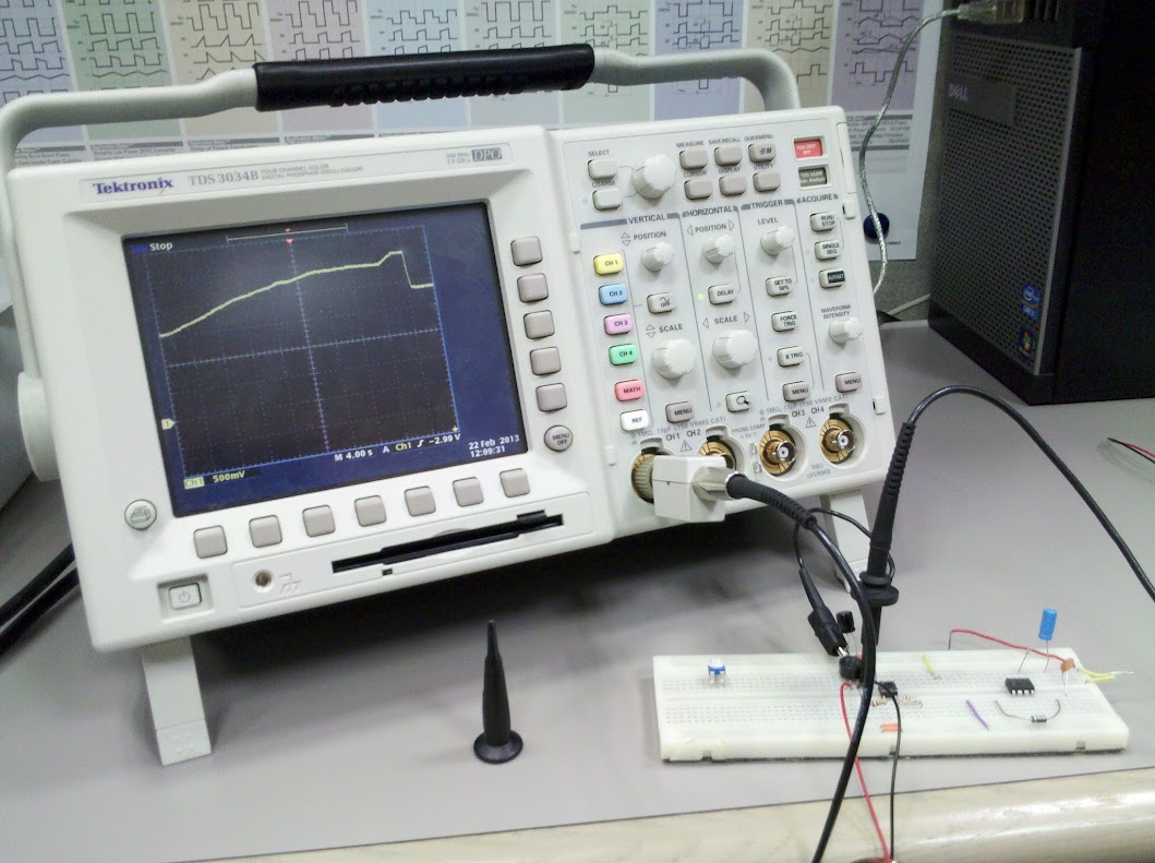 Test setup consist of piezo, diode rectifier, 100 [μF] capactor, diode and 2 [kΩ] resistor. Few gentle bends charge the capacitor allowing diode to light after button press.
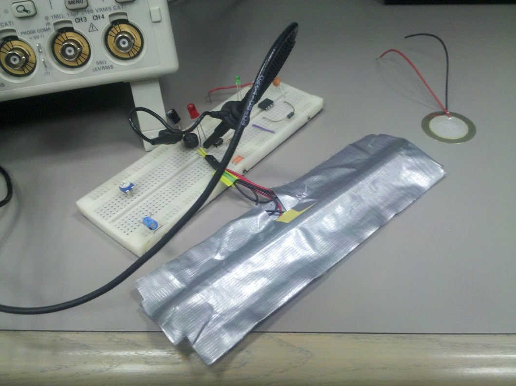 In this setup 4 piezos were connected in parallel to increase power. Rigid bar applies force to the centers of piezos. Piezos are mounted on soft base allowing them to bend slightly.
This setup produces much higher voltage on capacitor.
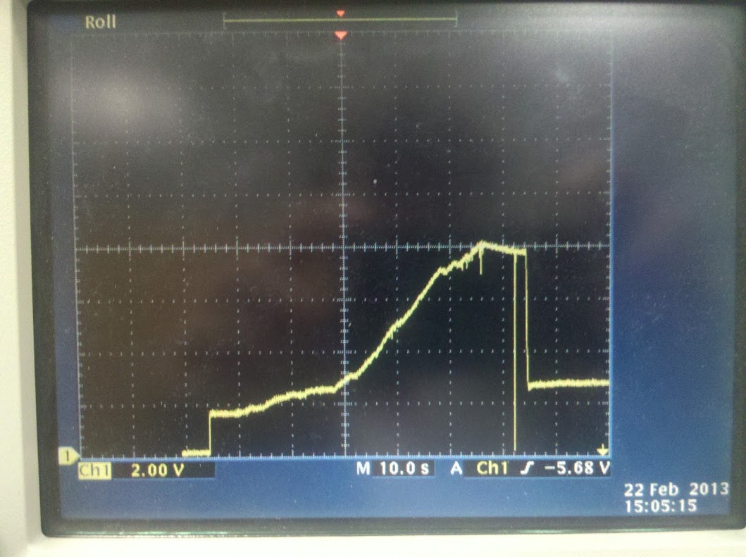 I was able to charge capacitor easily up to 6V.
Piezos are made of solid material and will break if applied force is too high. Broken piezo will produce much less power if any at all.
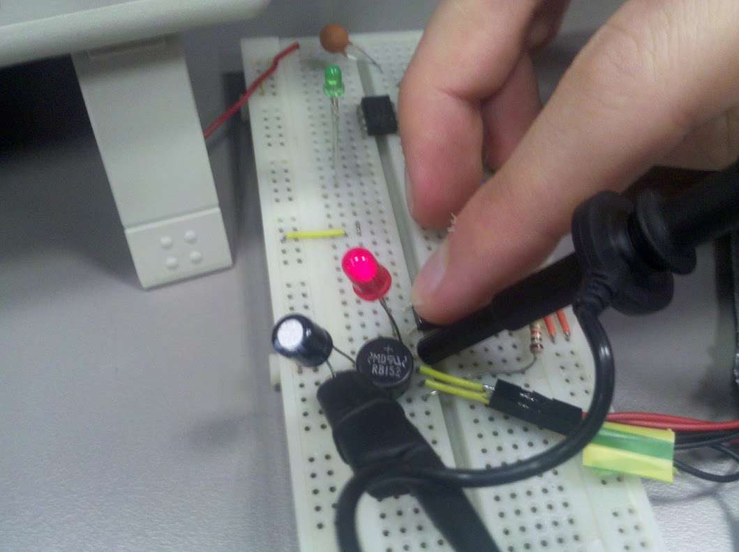 Close-up of the setup. The LED is bright.
Maybe this simple method of energy generation could be used for powering “active” cat's eyes on roads?
Hardware
Hardware design considerations:
- Low leakage current capacitors
- Maximum radio power - folded dipole antenna
- Low cost - minimal board size, components on one side
Schematics
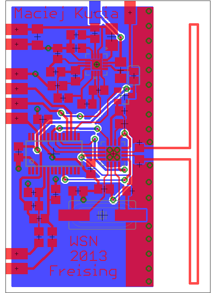
Layout
Software
Application is simple and can be represented by following flow diagram:
<html> <?xml version=“1.0” encoding=“UTF-8” standalone=“no”?> <!– Created with Inkscape (http://www.inkscape.org/) –>
</html>
After power-up MCU initializes all peripherals and goes into deep sleep. Two external interrupts are responsible for measuring the vehicle speed. First interrupt starts timer, the second one stops it and stores time in FRAM. If timer overflow occur measurement is discarded. After several measurements MCU activates radio, sets it and burst data stored in FRAM.
Summary
- GHz radio might be attenuated by asphalt. More experiments are required to estimate the best radio settings for minimal power and usability.
Prototype
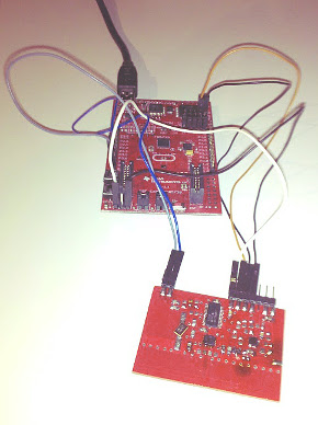
The device is connected to MSP-EXP430FR5739 for debugging and control signals emulation.
References
Datasheet
Application note
Other
- Estimation of Electric Charge output for Piezoelectric Energy Harvesting - Henry A. Sodano and Daniel J. Inman Center for Intelligent Material Systems and Structures Virginia Polytechnic Institute and State University 2004