Table of Contents
Sensor fusion
Overview
The aim of this project is to learn sensor fusion algorithms and implement them on ARM microcontroller.
GY-80
GY-80 is a cheap sensor board. Available on Ebay and DealExtreme.

Board feature 4 sensors providing in total 10-dimensional information.
Project assumptions
The purpose of this project is to provide sensor fusion solution using low-cost sensor board.
Phase I
- Build a I2C ↔ PClink
- Set up sensors
- Read data periodically
- Plot the data
<html> <?xml version=“1.0” encoding=“UTF-8” standalone=“no”?> <!– Created with Inkscape (http://www.inkscape.org/) –>
</html>
Launchpad connections
- Serial transmission parameters:
115200 8N1
| 1.1 | GY-80 VCC_3.3V |
| 1.10 | GY-80 SDA |
| 1.9 | GY-80 SCL |
| GND | GY-80 GND |
Source code
Screenshots
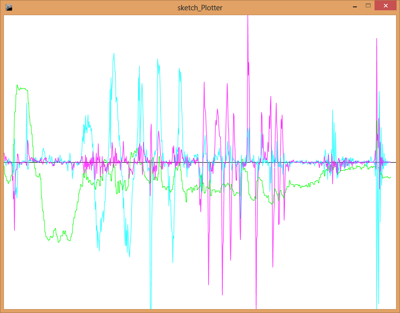
Notes:
- Scaling is being adjusted in real time, shake sensor board to set maximum values so graph can be scaled to fit the window.
- Keys
1to-turn on/off plotting value - Key
cclears the window
Phase II
- Implement 1D Kalman filter
Screenshots

Notes:
- Key
k- toggles filtered graph - Key
m- toggles measured value
Source code
- ARM code unchanged
Phase III
- 2D Sensor fusion
Following graph show angle measurement using accelerometer (red) and gyroscope (blue). Gyro clearly shows error-induced drift.
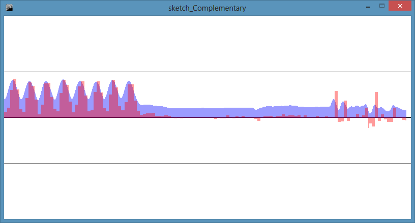
Complementary filter
<html> <?xml version=“1.0” encoding=“UTF-8” standalone=“no”?>
</html>
Complementary filter is a good alternative for small systems. http://web.mit.edu/scolton/www/filter.pdf
Comparison
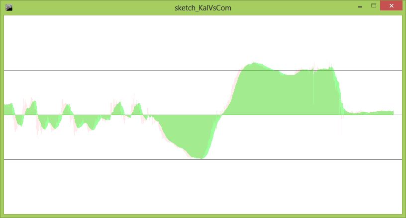
Filters:
- Red - Complementary
- Green - Kalman
While both methods provided unbiased value, the Kalman filter provided more stable readout. Present-day MCUs provide sufficient power to use Kalman filter in real-time.
Phase IV
- Build balancing robot.
The robot consists of 5 parts: Tamiya gearbox, double H-bridge driver, Bluetooth wireless module, Stellaris launchpad board and GY-80 sensor board. The power is provided externally.
GY-80 board provides accelerometer and gyro sensor measurement at 100 [Hz] (UPS variable). Sensor data is then processed by kalman filter and feed into PI controller. Control signal is driving PWM output driving motors H bridges.
Notes:
- The stability is good but not perfect
- Kalman filter response was rally bad. I have boosted the response by multiplying angular acceleration value. Estimated angle value has overshot now but is fast enough.
- Robot motors are powered externally. Wires are influencing robot stability.
- Taller robot would be much better (bigger moment of inertia).
- Both robot wheels are independent. Connected wheels would work much better reducing yaw.
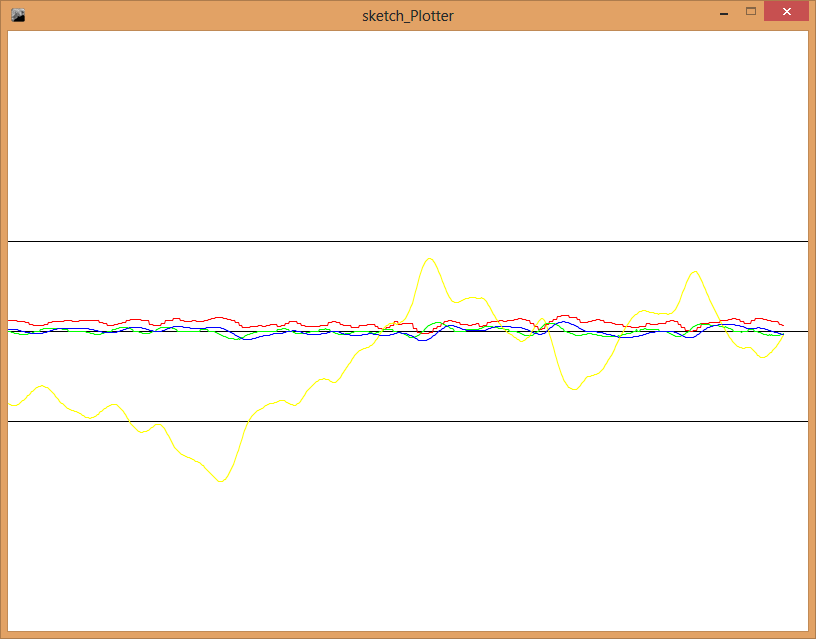 Robot operation. Red - accelerometer angle. Green - Gyro angular acceleration. Blue - estimated angle. Yellow - PI control signal.
References
- An Introduction to the Kalman Filter - SIGGRAPH paper by Greg Welch and Gary Bishop
- The Balance Filter - MIT presentation by Shane Colton
- tkjelectronics blog - A practical approach to Kalman filter and how to implement it